Global Adaptive Lyapunov-Based Control of a Robot and Mass-Spring System Undergoing An Impact Collision
Introduction
The control of dynamic systems that undergo an impact collision is both theoretically challenging and of practical importance. If the impact dynamics are not properly modeled and controlled, the impact forces could result in poor system performance and instabilities. One difficulty in controlling systems subject to impacts is that the dynamics are different when the system status changes suddenly from a non-contact state to a contact state. Another difficulty is measuring the impact force, which can depend on the geometry of the robot, the geometry of the environment, and the type of impact. As stated in [19], the appeal of systems with impact conditions is that short-duration effects such as high stresses, rapid dissipation of energy, and fast acceleration and deceleration may be achieved from low-energy sources.
Many researchers have investigated the modeling and control of impact systems including: [1]-[5], and [8]-[23]. Chiu and Lee developed a controller which is robust with respect to the uncertainties in environment dynamics for a linearized model of a manipulator undergoing an impact collision with a static environment in [4]. Specifically, by modeling the impact dynamics as a state dependent jump linear system, Chiu and Lee were able to apply a modified stochastic maximum principle for state dependent jump linear systems to optimize the approach velocity, the force transient during impact and the steady state force error after contact is established. In [20], a nonlinear impact control strategy was developed for a robot manipulator experiencing a "hard-on-hard" impact with a static environment. The controller in [20] was based on the concept that negative proportional force gains, or impedance mass ratios less than unity, can provide impact response without bouncing. The regulation of a one-link robot that undergoes smooth or non-smooth impact dynamics was examined in [19]. In [18], a two degree-of-freedom (DOF) planar manipulator was globally asymptotically regulated to contact an infinitely rigid and massive surface where the impact force was estimated using a reduced-order observer. An infinitely rigid mass is also considered in [15], where the desired time-varying planar motion of a mass is controlled within a closed region defined by an infinitely massive and rigid circular barrier. A reduced-order observer was also used in [10] to control the impact between the end-effectors of two cooperating manipulators where the exact knowledge of the robot dynamics and stiffness of the contact was required. In [21], methods are introduced to evaluate impact and contact forces on single and multiple robot manipulators.
In [2], a class of switching controllers was examined for mechanical systems with differentiable dynamics subject to an algebraic inequality condition and an impact rule relating the interaction impulse and the velocity. The analysis in [2] utilized a discrete Lyapunov function that required the use of the Dini derivative to examine the stability of the system. In [17], Sekhavat et al. utilized LaSalle's Invariant Set Theorem to prove the stability of a discontinuous controller that is designed to regulate the impact of a hydraulic actuator with a static environment where no knowledge of the impact dynamics is required. A switching controller was proposed in [22] to eliminate the bouncing phenomena associated with a robot impacting a static surface. The structure of the switching controller in [22] was dependent on impact feedback from a force sensor. In [16], a stable transition controller is proposed to deal with the transition from a non-contact to a contact state where explicit knowledge of the impact model is not required. Lee et al. developed a hybrid bang-bang impedance/time-delay controller that establishes a stable contact and achieves the desired dynamics for contact or non-contact conditions in [12].
Several controllers have been developed for underactuated systems that have an impact collision. For example, a family of dead-beat feedback control laws was used in [3] to control a class of juggling-like systems. One of the contributions in [3] is a study of the intermediate controllability properties of the object's impact Poincaré mapping. A proportional-derivative (PD) controller was developed in [11] to address global asymptotic stabilization of under-actuated mechanical systems subject to smooth impacts with a static object. In our previous work in [9], a nonlinear energy-based controller is developed to globally asymptotically stabilize a dynamic system subject to impact with a deformable static mass. The contribution in [9] is that the underactuated states are coupled through the energy of the system as a means to mitigate the transient response of the unactuated states. In [8] a backstepping approach is used to globally asymptotically regulate the impact of two systems where the exact system dynamics are known.
Several trends are apparent after a brief review of literature investigating the control of systems subject to impact collisions. Most controllers (e.g., [18], [20]) target "hard-on-hard" impacts with a static environment for a fully actuated system. Many researchers also exploit switching or discontinuous controllers (e.g., [2], [17], [22]) to accommodate for the impact conditions. This paper considers a class of fully actuated dynamic systems that undergo an impact collision with another dynamic system that is unactuated. The dynamic model for both systems and the impact force are assumed to have uncertain parameters. There are numerous challenging and practical applications that motivate this study including: the capture of disabled satellites, spaceport docking, manipulation of non-rigid bodies, biped robotics, and so on. This paper is specifically focused on a planar robot colliding with a mass-spring system as an academic example of a broader class of such systems. The control objective is defined as the desire to command a robot to collide with an unactuated system and regulate the resulting coupled mass-spring robot (MSR) system to a desired compressed state while compensating for the constant, unknown system parameters. The collision is modeled as a differentiable impact as in recent work in [11], [19], and our previous efforts in [8] and [9]. Adaptive Lyapunov-based methods are used to develop a continuous adaptive controller that yields global asymptotic regulation of the mass and robot links. Two linear parameterizations are designed to adapt for the unknown robot and mass parameters. A desired time-varying robot link trajectory is designed that accounts for the impact dynamics and the resulting coupled dynamics of the MSR system. The desired link trajectory converges to a setpoint that equals the desired mass position plus an additional constant that is due to the deformation of the mass. A force controller is then designed to ensure that the robot link position tracking error is regulated. Unlike some other results in literature, the continuous force controller does not depend on measuring the impact force or the measurement of other acceleration terms.
Experimental Results
The testbed depicted below was developed for experimental demonstration of the proposed controller. The testbed is composed of a mass-spring system and a two-link robot. The body of the mass-spring system includes a U-shaped aluminum plate (item (8) in the figure) mounted on an undercarriage with porous carbon air bearings which enables the undercarriage to glide on an air cushion over a glass covered aluminum rail. A steel core spring (item (1) in the figure) connects the undercarriage to an aluminum frame, and a linear variable displacement transducer (LVDT) (item (2) in the figure) is used to measure the position of the undercarriage assembly. The impact surface consists of an aluminum plate connected to the undercarriage assembly through a stiff spring mechanism (item (7) in the figure). A Precision capacitance probe (item (3) in the figure) is used to measure the deflection of the hard spring system. The two-link robot (items (4-6) in the figure) is made of two aluminum links, mounted on 240.0 Nm (base link) and 20.0 Nm (second link) direct-drive switched reluctance motors. The motors are controlled through power electronics operating in torque control mode. The motor resolvers provide rotor position measurements with a resolution of 614400 pulses/revolution. A Pentium 2.8 GHz PC operating under QNX hosts the control algorithm, which was implemented via Qmotor 3.0, a graphical user-interface, to facilitate real-time graphing, data logging, and the ability to adjust control gains without recompiling the program. Data acquisition and control implementation were performed at a frequency of 2.0 kHz using the ServoToGo I/O board.
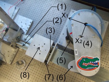
Figure 1
The the tip of the second link of the robot was initially 224 mm from the desired setpoint and 194 mm from impact along the X1-axis (see Figure 1 above). Therefore, once the initial impact occurs, the robot is required to depress the spring (item (1) in Figure 1 above) to move the mass 30 mm along the X1-axis. The mass-spring and robot errors (i.e., e(t)) are shown in Fig. 2. The peak steady-state position error of the robot tip along the X1-axis (i.e., |er1(t)|) and along the X2-axis (i.e., |er2(t)|) are 0.212 mm and 5.77 μm, respectively.The peak steady-state position error of the mass-spring (i.e.,|em(t)|) is 2.72 μm. The 0.212 mm maximum steady state error in |er1(t)| is due to the Ydˆθdk(t) term of xrd1(t) in (19) where Yd(t) = xm − x0 is very close to 0.03 [m] andˆθ dk(t) = ksKI has the maximum value of 0.007 at steady state which generate a 0.21 mm error. All the other terms in er1(t) are neglectable at steady state.
The input control torques (i.e., J T (q)F
(t)) are shown in Fig. 3 and Fig. 4. To constrain the impact force to a level that ensured the
aluminum plate did not flex to the point of contact with the capacitance
probe, the computed torques are artificially
saturated. Fig. 3 depicts the computed torques, and Fig. 4 depicts the actual
torques (solid line) along with the computed torques (dashed line). The
resulting desired trajectory along the X1-axis (i.e., xrd1(t)) is depicted in
Fig. 5, and the desired trajectory along the X2-axis was chosen as xrd2 = 370
mm. Fig. 6 depicts the value of ˆθ dk(t)∈R and Fig. 10-12
depict the values of ˆθr(t) ∈ R10. The order of the curves in the plots
comes from their scales rather than their numerical order in ˆθr(t).
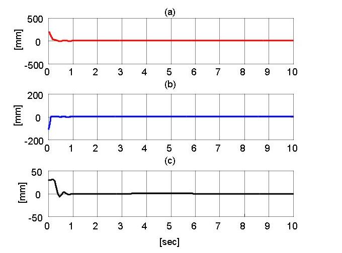
Fig. 2. The mass-spring and robot errors e(t). Plot (a) indicates the position error of the robot tip along the X1-axis (i.e., er1(t)), (b) indicates the position error of the robot tip along the X2-axis (i.e., er2(t)), and (c) indicates the position error of the mass-spring (i.e., em(t)).
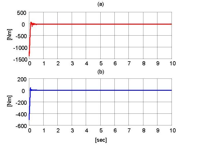
Fig. 3. Computed control torques J T (q)F (t) for the (a) base motor and (b) second link motor.
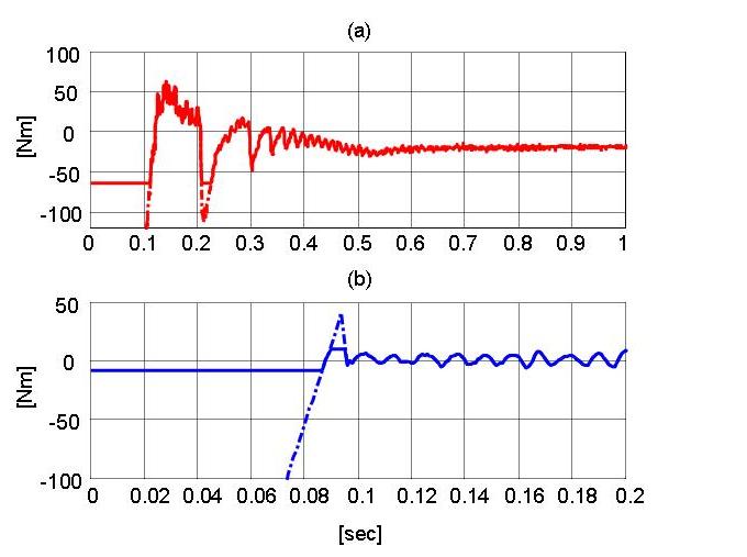
Fig. 4. Applied control torques J T (q)F (t) (solid line) versus computed control torques (dashed line) for the (a) base motor and (b) second link motor.
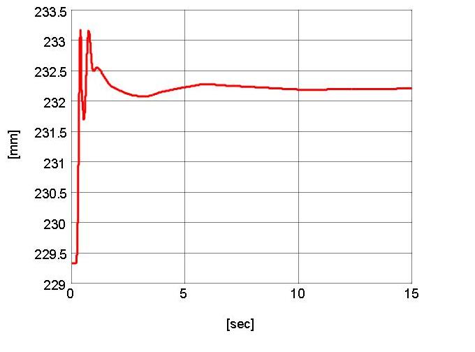
Fig. 5. Computed desired robot trajectory, xrd1(t).
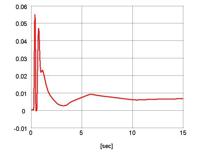
Fig. 6. Parameter estimate ˆθdk(t).
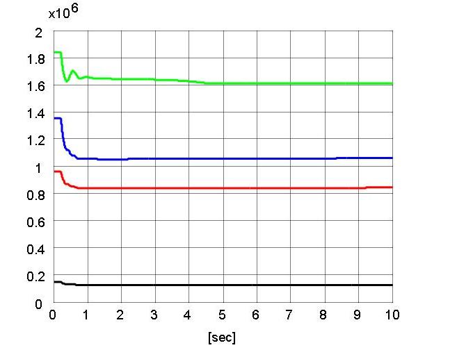
Fig. 7. Estimate for the unknown constant parameter vector ˆθr(t) a)ˆθr10(t) b)ˆθr4(t) c)ˆθr1(t) d)ˆθr7(t)
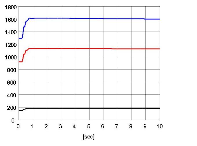
Fig. 8. Estimate for the unknown constant parameter vector ˆθr(t) a)ˆθr5(t) b)ˆθr2(t) c)ˆθr8(t)
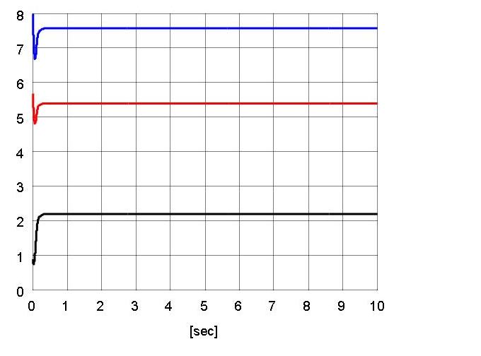
Fig. 9. Estimate for the unknown constant parameter vector ˆθr(t) a)ˆθr6(t) b)ˆθr3(t) c)ˆθr9(t)
A movie of the experiment is provided below.
Publications
K. Dupree, C. Liang, G. Q. Hu, and W. E. Dixon, Global Adaptive Lyapunov-Based Control of a Robot and Mass-Spring System Undergoing An Impact Collision, IEEE Conference on Decision and Control, San Diego, CA, 2006, pp. 2039-2044.